Device Testing
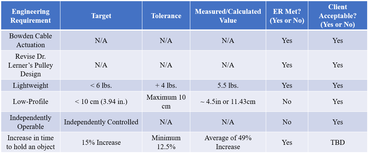
We began our testing with the easy tests first. The Finalized Testing Plan report details our testing procedure for each of these experiments. Our "Cable Actuation" and "Pulley Utlization" tests visually inspected if the device incorporated either of those components. Next was the protrusion and weight test. Here we measured how far the device protruded off the body and we measured the total weight of the device including all of its components. The results from these tests can be seen in the specification sheet located on this page.
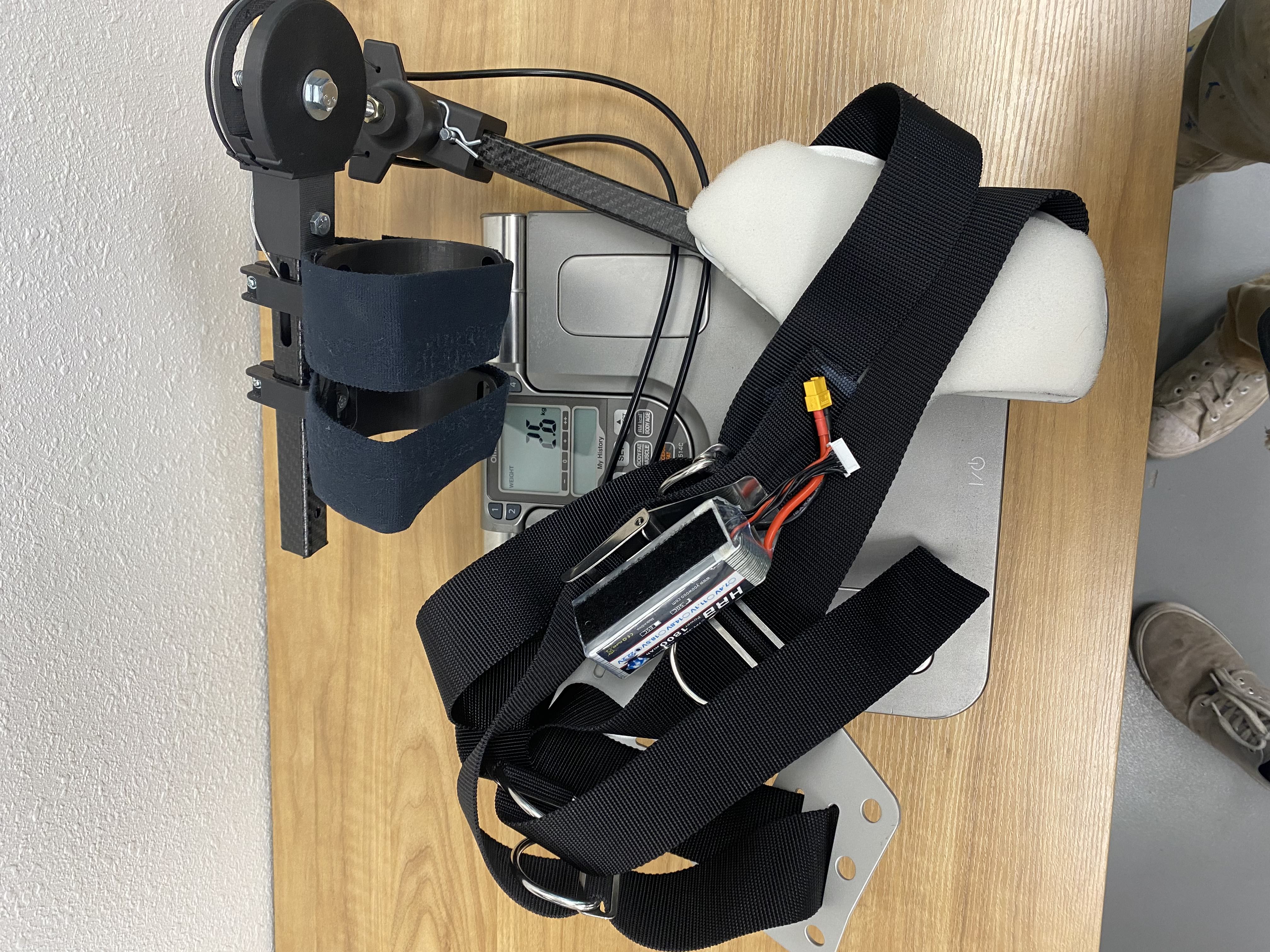
For the weight test, we placed the device onto a scale from Dr. Lerner's lab. The completely assembled device was placed on the scale in order to get an accurate reading of the total weight. This included the battery, motor, harness system, etc. The total weight measured from this scale was 2.6 kg or 5.73 lbs.
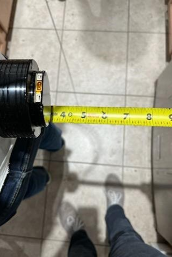
For the protrusion test, we used a tape measurer to determine the maximum protrusion of the device. We measured at all points that were visually the highest extrusion. For our device, this was the pulley, motor, and block. Our design requirement was to remain under 10 cm (3.94 in.) of protrusion from the body. In the images below, the measured value was about 4.5in for the block and just over 4in for the motor. The pulley extruded less than both these values. Unfortunately, these protrusions do exceed the design requirement, however this is still acceptable by the client as seen in the spec sheet.
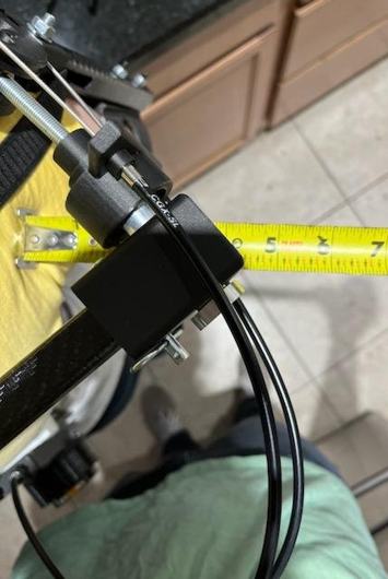
Block Protrusion
Motor Protrusion
In order to perform the endurance test the team needed to test the functionality of the motor. A lot of the testing had no results and the code would not make the motor move. Occaisonally the motor would immediately send a force output to quickly that would result in it flipping the device. The video cannot be embedded here but you can click this link to view it. Once the team got the code to work they put the device on a user to see if the motor would still supply a force with resistance. Unfortunately, the team forgot to lower the force output for this test and sent 8 N-m of force from the motor to the shoulder. This broke the device shown in the video to the left.
The piece that broke in the above video was the shaft found on the block that interfaced the pulley with the rear bar. This shaft was designed as one component connected with the block and was printed out of PLA only. PLA is far from strong enough to handle the load sent through it during the test so Dylan machined an aluminum shaft inside the NAU machine shop to replace this component. The rest of the block was reprinted with Onyx inlaid with carbon fiber to add extra strength to its component.
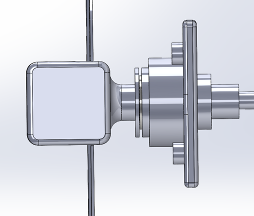
Original Shaft Design - PLA
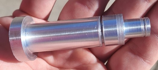
Revised Aluminum Design
Our test subject in these videos is graduate student Daniel Colley. Daniel currently works in Dr. Lerner's Biomechatronic's lab and is developing his own elbow exoskeleton. These videos depict our endurance test which has been the project goal from the start. The user will wear the device but won't have any assistance supplied to them. Their task is to hold the weight (backpack) in front of them with a 90° bend in their elbow, as shown in the video, for as long as they can while maintaining that angle with their elbow. This helps drive the weight of the backpacke into the arm where the device is able to assist. Once the user can no longer maintain the 90° angle the timer is stopped and their time to hold the object is recorded. The user is allowed a 5 minute rest time and the process is repeated for various test subjects either assisted or unassisted.
In this video, Daniel is performing the same endurance test but assisted. The assistance is seen in the stiffness of the device.In the last video the pulley component is not rigidly straight, however in this test you can see the arm bar abruptly try to straighten itself. This is the due to the controller individual enacting the torque output by the motor. A pressure sensor is used to apply tension in the cable in one direction, and another sensor is used to apply the tension in the other direction. Once the finger is taken off the pressure sensor the motor will immediately stop supplying any force. In this assisted test, the motor is outputting 7 N-m of force which becomes 21 N-m at the shoulder due to the gear ratio of the system. This 21 N-m of force is enough for the user to notice a supplied assistance but it is not enough for the user to completely relax their arm and do no work. This slight assistance from the device allows the user to hold the weight for longer times and in the case of Daniels testing, he experienced approximately a 20 second increase in trials.
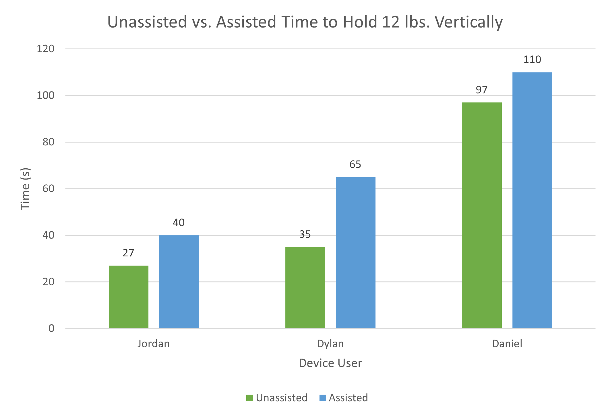
We expected that our device would be able to increase the timed ability of a user to hold a weight in front of them. From our endurance test, we found that each test subject experienced an increase in time to hold a weight while assisted versus unassisted. The team is ecstatic to have gotten these kinds of result. Future testing will be done to refine these numbers by conducting more trials, but due to the nature of this submission those results cannot be present now. The testing results and final spec sheet are pictured below.