This gallery reads from left to right, top to bottom, in the order of design iterations created by the team throughout the duration of the project. The final design is located at the bottom but is discussed in more detail in the testing section.
Prototype 1 - Fall 2022 | Alt Image
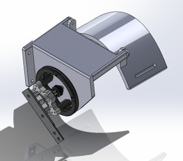
This was the first prototype we developed which was submitted at the end of the fall semester in 2022. This hinge design was mounted to the shoulder using a cuff fitted to the shape of the shoulder. The pulley design is Dr. Lerner's directly complete with the torque sensor interfaced with a carbon fiber bar which would connect to the arm. At this point, we did not design a mount to the arm or housing components for the batteries and motor.
Prototype 2 - Ball and Socket | Alt Image
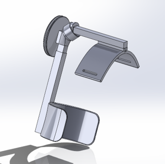
The second prototype we made utilized the same shoulder mounting but converted the hinge into a ball and socket. This allowed us to achieve the range of motion necessary for every day mobility. The pulley design was changed from a revolute joint to a static positioning which we figured out later would not work.
Prototype 3 - Revised Ball and Socket | Alt Image
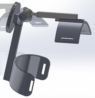
Prototype 3 is a replica of prototype 2 with some minor changes that made the design smoother. We added a sliding track to the shoulder to offer more freedom in the lateral range of motion. A cap was added to the ball to secure it to the socket. Crimp holes were added to the pulley which meant at this point we started thinking about how the Bowden cables would interface with the pulley.
Prototype 4 - Spring 67% Build | Alt Image
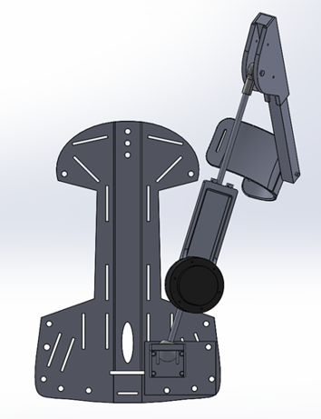
The creation of this prototype came from us not understanding the feasibility of the pulley mechanism. We design a pivot point that would interface with cable on either side, thus when one end was pulled the device would either move up or down. The scuba plate was introduced as the rigid mounting system to connect the accessories to the user's body. Unfortunately, the pivot point design strayed far away from the customer requirements and the team had to redesign.
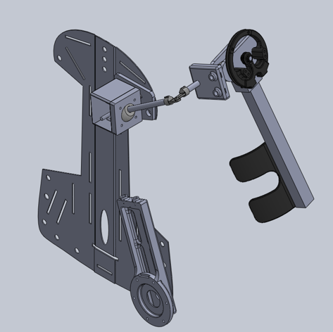
Prototype 5 - Redesign | Alt Image
This redesign phase caused a lot of panic for us on whether we would meet the 100% build or even have our design approved. This design kept most major components from prototype 4, but moved the ball and socket joint to the top of the back and connected it to the pulley with a hinge.
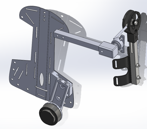
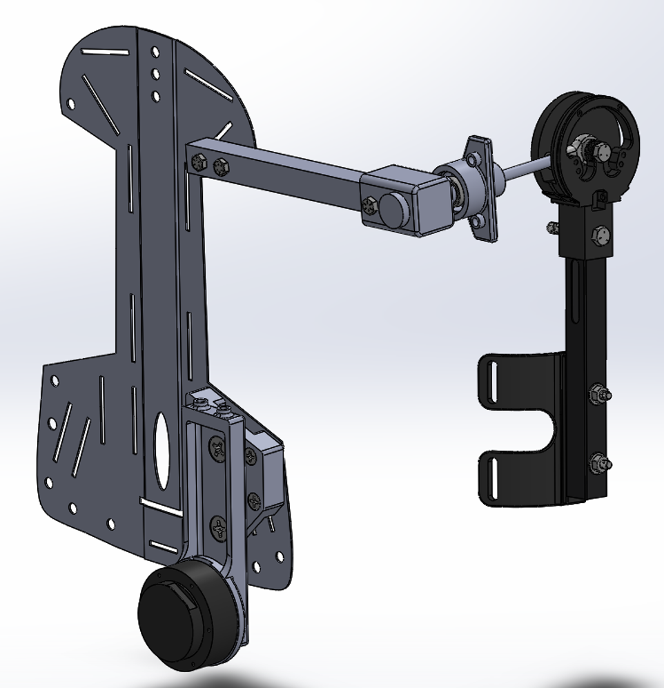
Prototype 6 - 95% Build | Alt Image
The team really did well with the design of prototype 5. This met all of the customer requirements and the client liked where the design was headed. The team found that the previous hinge was not rigid enough to complete the motions setup for testing so a carbon fiber tube was used to solidify the design. The new rigid bar connecting the pulley to the back allowed for assisted movement in only one degree of freedom and not all degrees. If there was assistance in all degrees of freedom then the user would experience their arm being pulled in every direction instead of just upwards.
Below is a video of our 33% Hardware Status update focusing on the demonstration of our device at that time. Check it out to see where our device started out and compare it to where we are now.