Phase 1
VDG concept
The original Van de Graaff path helped define the project goal, but it was not practical for controlled and repeatable testing.
This page goes deeper than the home page. It shows how the project moved from the original Van de Graaff concept into the current pulsed-discharge prototype, what has been built, what has been observed so far, and what still needs improvement.
The project has moved from concept work into a real bench-scale prototype. The chamber and HV system have been built, spark-gap discharge has been demonstrated, and preliminary CO₂ testing has been run through a handheld analyzer.
The original Van de Graaff path helped define the project goal, but it was not practical for controlled and repeatable testing.
The chamber, electronics, gas path, and bench setup have all been assembled into a working prototype.
After 30 seconds to 1 minute of runtime, the handheld analyzer showed CO readings peaking around 50 ppm.
The next phase is improving reliability, flow control, and validation with better gas diagnostics.
The project began with a Van de Graaff-based concept and then pivoted to a pulsed-discharge platform better suited to prototype control, measurement, and repeatable testing.
The original idea was to use a Van de Graaff generator to create a strong high-voltage discharge for CO₂ dissociation. That phase helped define the project goal, but it also showed that high voltage alone is not the same as controllable and measurable energy delivery.
Even though the Van de Graaff path was set aside, it clarified the real design requirements for the capstone: controllability, repeatability, safer staged bring-up, and a build that could be measured instead of only energized.
The current direction uses pulsed high-voltage discharge because it is more practical to build, easier to tune, and better suited for structured chamber testing. It also gives a clearer path toward shorter pulse operation later, even though true nanosecond pulses are not yet being achieved in the current build.
The current engineering direction is based on the idea that short-pulse, non-equilibrium plasma behavior is more promising for controlled CO₂ excitation than a purely thermal, open-air high-voltage discharge.
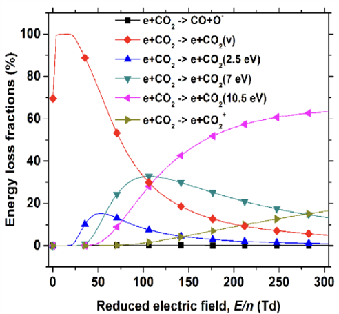
This figure supports the shift away from a more thermal approach and toward a pulsed-discharge strategy.
The chamber is designed around a defined discharge region, a controlled gas path, and a geometry that can be adjusted as testing improves.
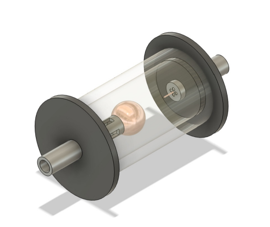
Concept render used to communicate the chamber direction and intended layout.

Integration of the chamber and supporting hardware during development and testing.
The present HV system uses an ESP32-S DevKit, a switching stage, transformer-based HV generation, and support hardware for lighting and gas-control functions.

Electrical architecture used for the present bench prototype.
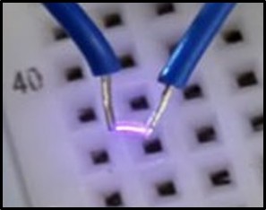
Real discharge output from the current HV setup during bench testing.
Early testing has moved beyond spark generation alone. CO₂ has been routed through the chamber during discharge, and the handheld analyzer produced a measurable CO reading.
The handheld analyzer was useful for an early indication, but it is not the final validation method for the project. The result now needs to be repeated under better-controlled conditions and compared against stronger gas-analysis tools.
The main limitations explain why the current results are still preliminary and why the next phase is focused on reliability instead of bigger claims.
Nanosecond pulse operation is still the goal, but it is not yet achievable in the current setup because of the PWM/control limitations of the present hardware.
The mass flow controller path was intended to support control and logged data, but the sensing/control chain did not work fully reliably in the current build.
The handheld analyzer gave a useful preliminary result, but higher-confidence gas-analysis tools are still needed before stronger claims can be made.
The next phase is about making the system more reliable, more measurable, and more defensible.
Improve electrical control and survivability so the discharge can be characterized more cleanly.
Improve the MFC path and make gas-flow control and logging more dependable.
Use stronger gas-analysis equipment to verify whether the observed CO readings are repeatable and real.
Refine chamber geometry, operating conditions, and system integration based on measured behavior.
High-voltage testing is treated as its own subsystem. Safety procedures, enclosure choices, staged bring-up, and documented changes are part of the engineering process.
Safe operation requires controlled power-up, clear grounding strategy, defined roles during testing, and careful documentation of any wiring change.
The chamber is housed in a microwave-based enclosure acting as a Faraday-cage-style housing, and gas hardware must be handled with the same level of care as the HV system.
One change at a time, documented settings, shielding, and staged bring-up matter just as much as the circuit itself.