
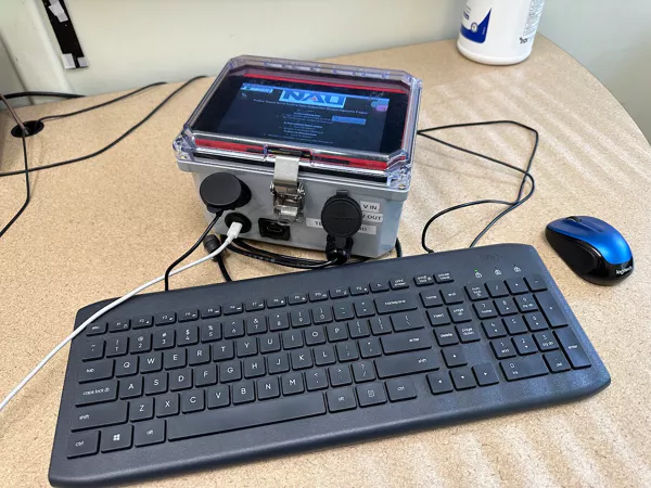
Final Hardware Design
The team was able to create a fully functional data
acquisition system that met all fo the customer and
engineering requirements. The enclosure was kept small
(6x8x4 in), the system is able to measure wind speed,
temperature, pressure, voltage, and current all within the
required ranges, and the system is safe and reliable. The
team utilized a 7" touch screen that allows the user to
easily access the system, or there are user interface ports
on the front like USB ports and an HDMI adapter to use the
system on a larger screen with a keyboard and mouse. The
front of the enclosure also has ports for USB c power in, a
cable gland for the temperature probe and cup anemometer,
and an Anderson Power pole adapter for voltage from the wind
turbine.
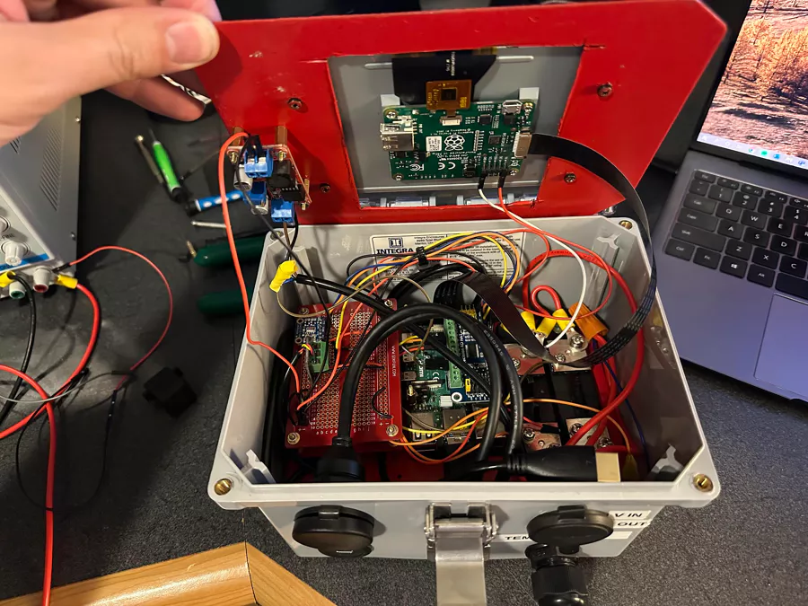
Final Hardware Design (internal)
To meet the requirements of the project, the team utilized
an electrical enclosure to house all of the parts needed
to create the system. This is an image of the enclosure
with both the screen base and the subpanel visible. The
screen base is used to mount the 7" touch screen as well
as the voltage amplifier for the anemometer. The subpanel
is used to mount the shunt resistors, the raspberry pi,
and the perf boards.
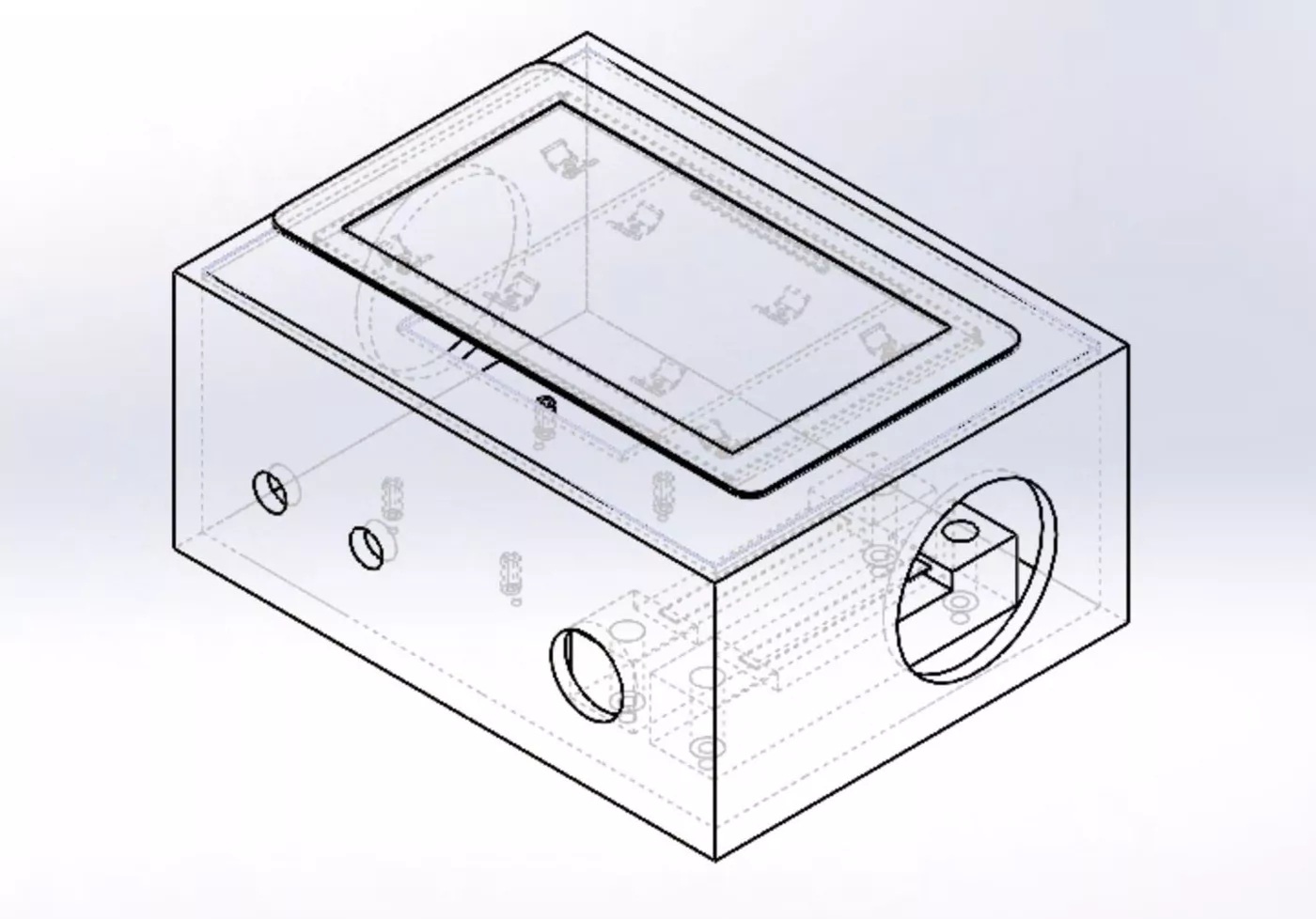
Enclosure Model
This image is a 3D model of what the team wants the PCC to
look like at the end of this project. The enclosure is a
NEMA suppy 8x6x4 inch ABS enclsoure that meets NEMA
standards for water resistance and durability. Holes will be
drilled on the bottom for cable glands and power pole
connectors. Holes on the sides are for in and out fans to
cool the internal electrical components. These fans will be
covered by shrouds and filters to maintain water resistance.
The customer will be able to interact with the screen
through a keyboard and mouse, or by lifting up the lid and
using the touch screen.
Enclosure
This is the updated enclosure as of the 33% build
presentation for Capstone 2. The enclosure was modified to
remove the large hole for the cooling fan, and smaller holes
were added for interface ports across the bottom of the
enclosure. The large cooling fan will be replaced with a
small fan that will be mounted directly to the raspberry
pi.
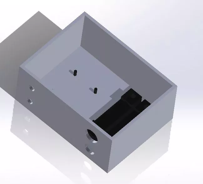
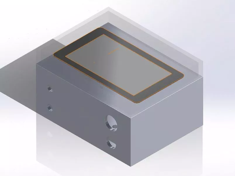
Enclosure Without Lid
This image shows the general layout of the inside of the
enclosure. The posts on the left will be the mounting spots
for the raspberry pi. The black objects on the right are
indicators of the locations for the shunt resistors.