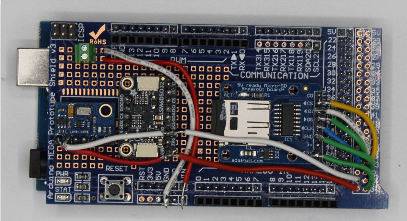
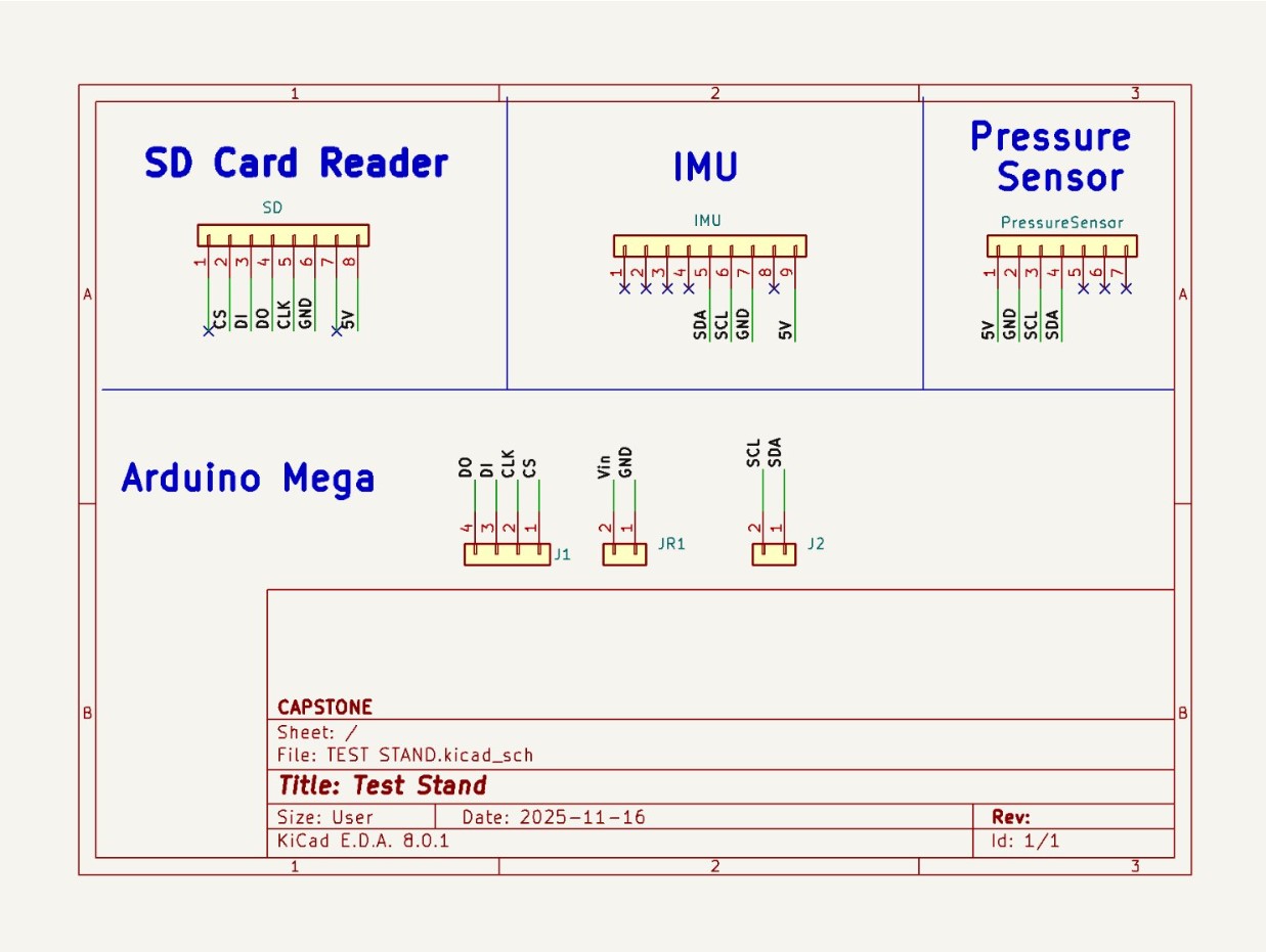
This is our second prototype for the flight computer that was used in our first two test flights where we gathered data and tested sensors. Here you can see the pressure sensor (left-most component), IMU (the component near the center), and SD card reader (right most component).
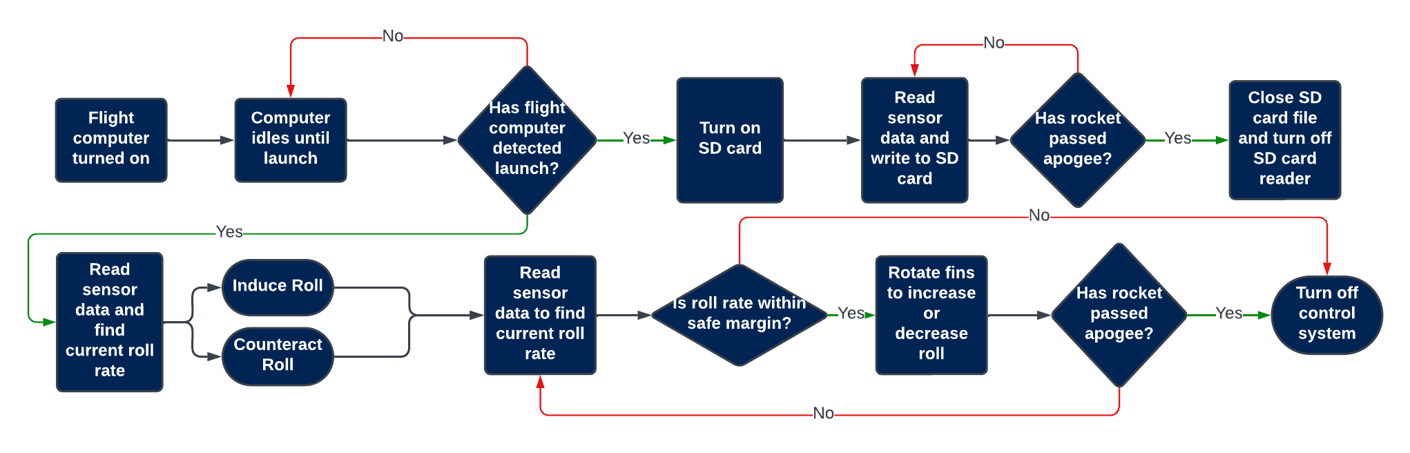
Flowchart of our flight computer program
The inertial measurement unit (IMU) is responsible for measuring the rotation and acceleration of the rocket. We need to ensure that it records information accurately in real-time. To test it we spun the test stand on a lathe at a known RPM (verified by both the lathe's RPM counter and by using a phone flashlight flashing at a set frequency). So far, this has been the only sensor we've tested.
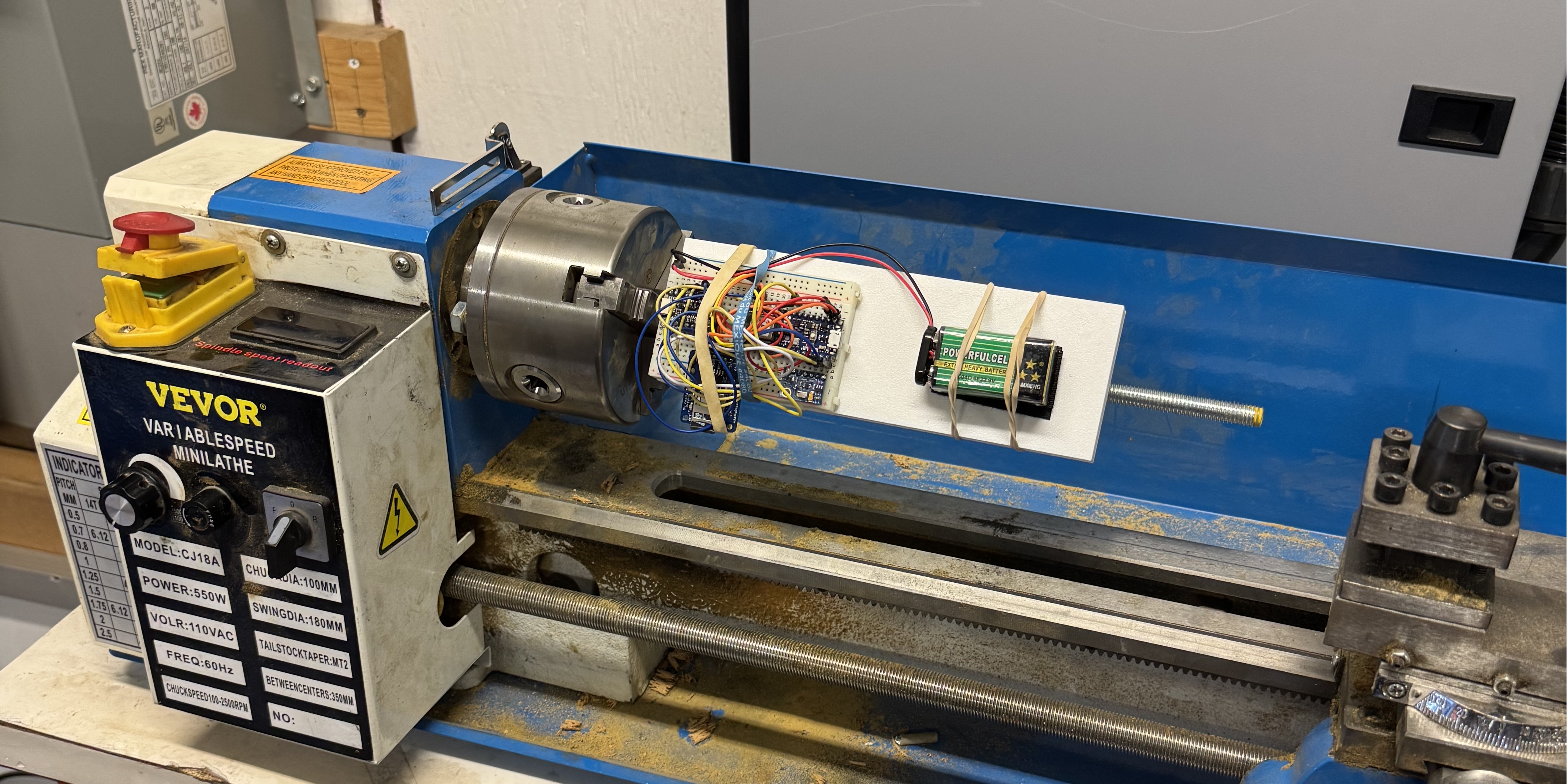
The above lathe test-bench gave us meaningful test data, in this example we spun the lathe at 100 RPM. The data's average is 100 RPM. This is great, but we need accurate live data. So we need to implement filtering to smooth over some of the peaks and valleys.
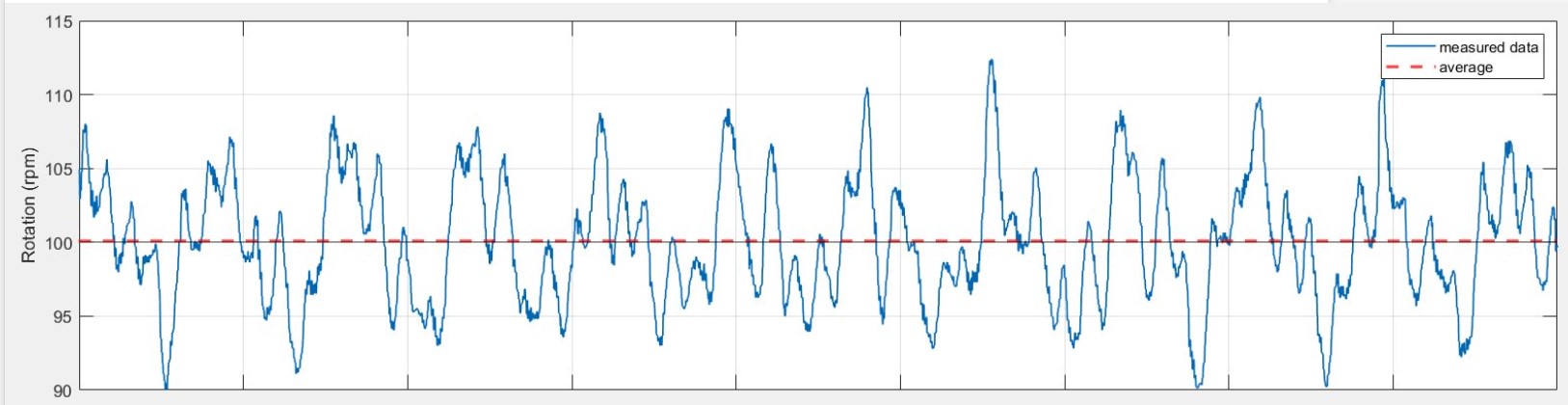
Raw data before filtering
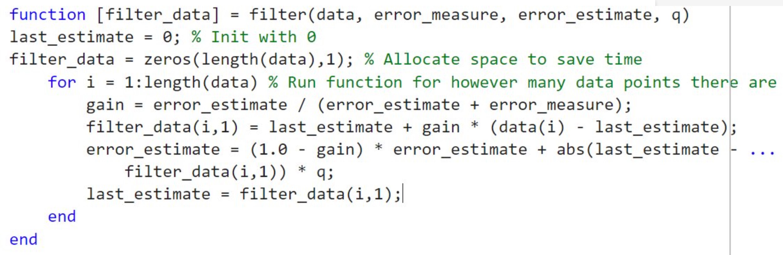
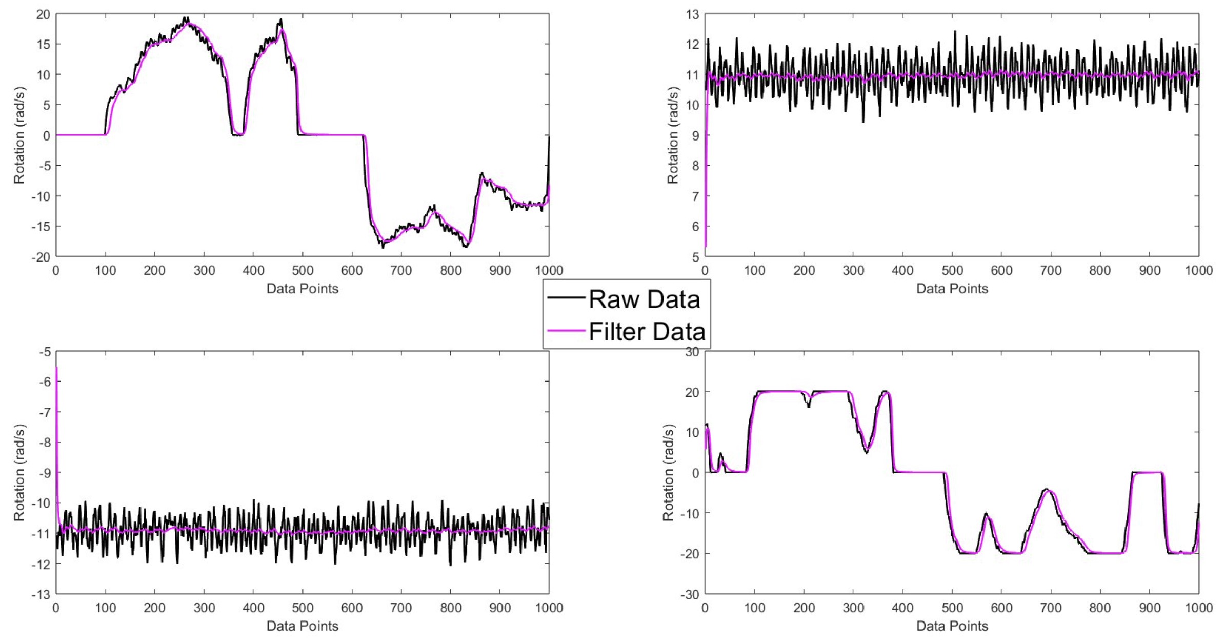
To smooth out the noise in our sensor data, we implemented a digital filter that reduces peak and valley spikes while preserving the overall trend of the data. This filtering technique allows us to get more reliable real-time measurements for our control system feedback.
Collect initial flight telemetry from the rocket.
Incorrect firmware was uploaded to the flight computer prior to launch.
The rocket launched successfully, but no sensor data was recorded.
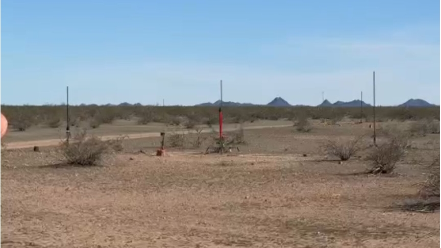
Induce a roll to verify the sensor is capturing data properly. Note the spin of the rocket in the video.
The flight was successful, and the sensor data was captured as expected.
Complete and successfully launch a working demonstration of the control system. Two launches were supposed to happen same day:
- 0 RPM demonstration (shown in video)
- 100 RPM (not shown due to running out of time on launch day)
Three main issues:
- Fin misalignment caused rocket to spin out-of-control at launch.
- The servo was limited to +/-5 degrees of center.
- Safety feature prevented the control system from activating until 8 seconds into the launch, so it didn't have enough time to correct the spin before apogee.
Take note of the three graphs overlayed on the rocket POV video:
- Top left: angle of attack stays at 0 and maxes out at 8 seconds due to the safety feature preventing the control system from activating prior to 8 seconds. (note: angle of attack is in measured in radians, not degrees)
- Top right: when y or z exceeds 5 rad/s the control system deactivates, you can see when it dips below 5 rad/s is right around 8 seconds, where the control system turns on.
- Bottom right: shows where apogee occurs in the flight where the lines converge.
The final launch was unsuccessful due to the aforementioned issues, and there was not an opportunity to do a second launch for the 100 RPM demonstration.