


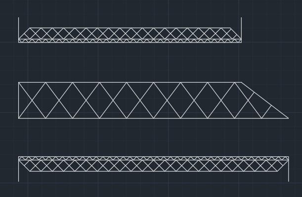


The design phase began with the team creating a set of sketches, for brainstorming purposes. Sketches were created by hand or in AutoCAD. There was no limit to the number or style of the sketches, the only guidance was to keep in mind the number of connections, in attempt to keep construction time at a minimum. A total of 10 sketches were created. The sketches created by the team are shown to the right.


With three functional models, a decision needed to be made to move forward to reach a final design. A decision matrix was used to score each model. Bridges were scored based on lateral and vertical deflection, weight, constructability, and aesthetics. Weight and Constructability were weighted the highest at 30% as these categories impact the competition results the most. Lateral deflection was the next highest at 20%, followed by vertical deflection at 15%. Lateral was weighted higher than vertical because the bridge needed to pass lateral to get the vertical load tested. Aesthetics were weighted the least because functionality was considered more important than looks.
Within the decision matrix actual values were listed to be used in scoring. Aesthetics were ranked 1, 2, or 3 with 3 being the best. To determine the raw score, the highest value was given a score of 1, then the remaining bridges actual score was divided by the highest for that category. Raw scores were then weighted and all categories were totaled to determine the overall bridge score. A lower score is favorable.
Option 1 and Option 2 scored closely, which lead to both moving forward to be refined. Both models were modified with the goals in mind of decreasing weight, number of pieces, and deflections. Once the models had been improved another decision matrix was used to select one model. Scores were determined the same way in the second decision matrix, and ultimately led to Option 2 being selected, as shown below. This selection was not the final model, just the only model that would be further improved.

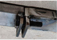
To design bolted connections, first the number of unique connections needed was identified. It was determined that there would be 4 unique connections; one for the top of each truss member: one for the bottom of each truss member, one for straight cross bracing, and one for diagonal cross bracing. The SSBC rules were referenced for the design of each connection as they had specific constraints, such as the number of faying surfaces (times the face of a member touches another). The unique connections are shown below.
Using the AISC Steel
Construction Manual, the number of bolts required for each connection was determined to ensure each connection would be adequate for
all failure modes. A similar process was followed to design welded connections. Unique weld styles were determined at appropriate bridge locations. Calculations were completed to determine the strength of the weld and base material.


Connection 2: Top of Truss
Connection 3: Straight Cross Brace
Connection 1: Bottom of Truss
Connection 4: Diagonal Cross Brace
With design completed, the team went on to create a set of shop drawings. This plan set was crucial as Flagstaff High School (FHS) would be welding the bridge for the team. The drawings included a material and parts schedule, multiple views, and connection details.
See Shop Drawings


Summary of Results

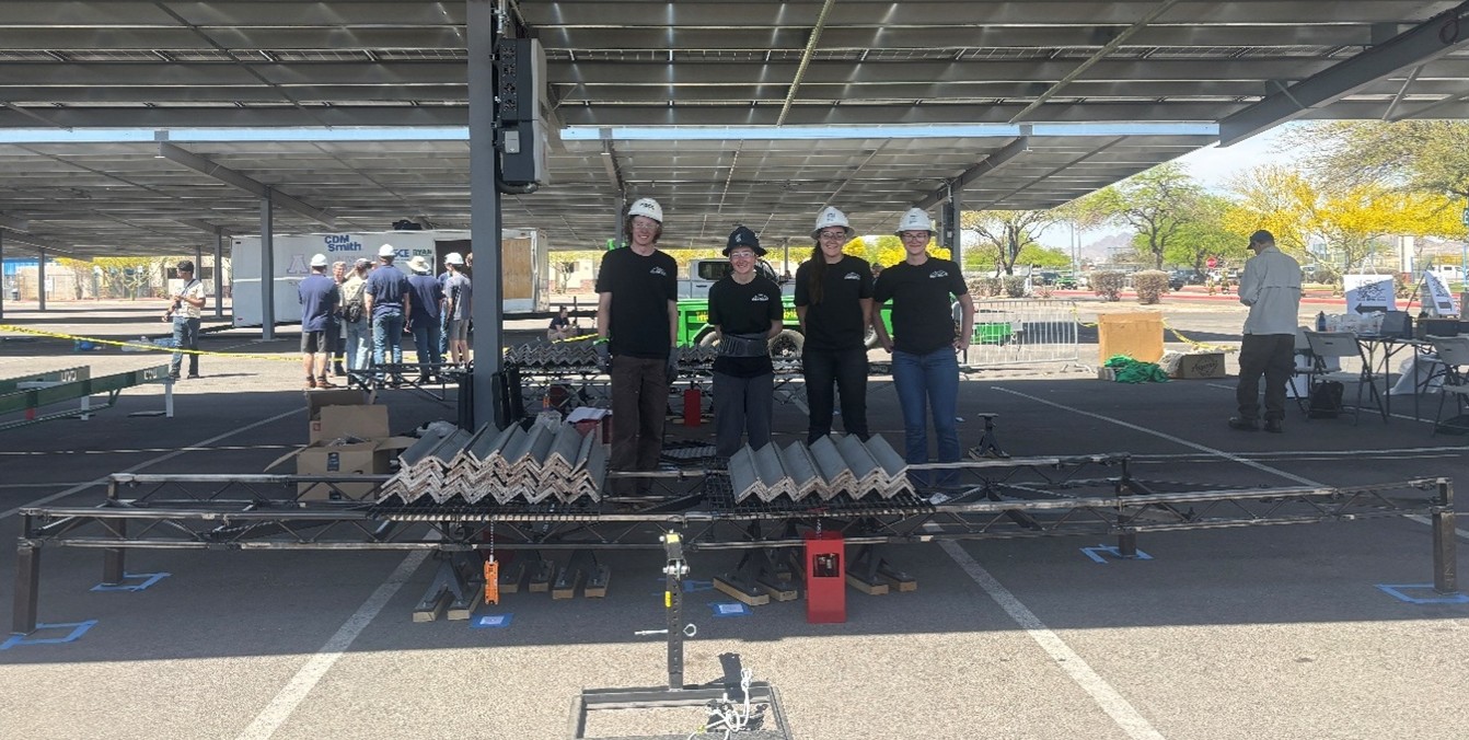
With fabrication complete, the team took their bridge to the Intermountain Southwest Student Symposium, where the bridge competed in the SSBC. At competition timed construction was completed, followed by lateral then vertical loading. The results of the competition were not ideal, but the team anticipated a larger deflection than the model predicted due to error in fabrication. Overall the team learned a lot about design, fabrication, and construction from this project and considers it a success.
This site was created with the Nicepage