

Munds Canyon Wash
Pedestrian Bridge
Cash Burger, Andrew Sayer, Ryan Emerick
Department of Civil Engineering, Northern Arizona University; Flagstaff,
Arizona
Conclusion
Residents
of Munds Park had expressed their concern to Coconino County
about the safety of pedestrians crossing Munds Canyon Wash using the
existing vehicle bridge. Therefore, the objective of this design
was to provide an alternative crossing over Munds Canyon Wash for
pedestrian and bicyclist traffic. To accomplish this goal a
new pedestrian bridge was designed to be constructed adjacent to
the existing vehicle bridge. More specifically the individual
tasks were to generate a site map in order to determine the
location of the new pedestrian bridge, design and place the
abutments for the bridge, and to select a prefabricated bridge for
implementation. Design constraints for the bridge were such that
all portions of the pedestrian bridge must be above or equal to the
lowest point on the existing vehicle bridge corridor. The placement of the
bridge was also limited to the south side of the existing vehicle
bridge. The bridge spans 110 feet and has an 8 foot wide
deck. The truss type selected for the design was a pony truss
with Pratt layout. The design was completed for Dale Wegner,
County Engineer for the Coconino County Public Works Department.
Furthermore, the pedestrian bridge design was developed in correlation
with the pedestrian sidewalk plans developed by Arizona
Engineering-GHD.
The location of the
pedestrian bridge and its abutments in relation to the existing
vehicle bridge and the surrounding area can be seen on the
following topographic map developed by CAR Engineering.

•Designed for a
max grade of 5% as per ADA Specifications
•Utilities run along
Pinewood Boulevard and existing vehicle bridge
and were found not to be an issue for the design or construction
of the abutments
•Bridge will be made of Corton Steel with synthetic planking for
the bridge deck.
•Design cannot impede on existing flow characteristics of the wash
•All limits of
construction are within the Right of Way
•Abutments designed to meet all codes, specifications, and standards
from:
•AASHTO
•ADA
•ACI
•AISC
•From the AASHTO, ADOT, and Coconino County guide specifications
for design of a pedestrian bridge:
vehicle live load = 10,000
lbs. (H5-truck)
Pedestrian live load = 65
psf
Snow load = 40 psf
Wind load = 35 psf
Seismic load =
Category C (Wind Controls)
Dead load = 54,400 lbs.
Total Factored Load =
174,400 lbs. (Vertical)
Total Factored Load = 27,720
lbs. (Lateral)
•Throughout the design process CAR Engineering's objective was
maintaining professionalism while never losing sight of the main
goal for this project: Ensuring Public Safety
•CAR Engineering provided a safe alternative for non vehicle traffic
and effectively separated vehicle and non vehicle traffic
•The proposed
design is within the approved project budget
•AISC Steel Construction Manual, Thirteenth Edition
• Americans with Disabilities Act (ADA)
•AASHTO Pedestrian Bridge Design Manual
• Ninyo and Moore Geotechnical Report
• American Concrete Institute Code (ACI)
•Das, Braja. Principles
of Foundation Engineering, Sixth Edition. Toronto: Nelson, 2007.
•Das, Braja. Principles
of Geotechnical Engineering, Sixth Edition. Toronto: Nelson, 2007.
•AASHTO LRFD Bridge Design Specifications, Third Edition
2004
ROSCOE
BRIDGE COMPANY
•CONTECH CONSCRUCTION PRODUCTS
•Coconino County Public Works Department
•Dale Wegner, PE
•Ken Godwin, EIT
•Jon Ebers, Project Manager
• Arizona Engineering-GHD
•Pinewood Boulevard East
Roadway Reconstruction and Storm Drain Plans
•Pinewood Boulevard Sidewalk
Plans
•Pinewood Boulevard Outlet Structure Plans
• McCormac,
Jack C., and James Nelson. Design of
Reinforced Concrete Seventh Edition.
Hoboken, New Jersey:
John Wiley & Sons, Inc., 2006.
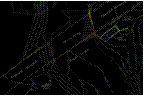
Topographic
Site Map
The existing outlet
structure shown on the Project Site Map
was originally a modified
ADOT standard single barrel box
culvert. As part of the design, this culvert was
built up using
4,000 psi concrete and
capped off in order to be used as an
abutment. The shaded area of
the figure below shows the
built up portion of the
outlet structure. The white area is the
existing outlet structure
before modification.
Built Up
Outlet structure
The cost for the project
includes engineering fees, materials,
and a construction cost
estimate based on similar projects
throughout Arizona.
Total Cost of Project =
$295,128.00
The approved budget for this
project is $300,000, with 93%
being federal money. Based
on CAR Engineering's cost
estimate, the project is
within the approved budget.
Design By: CAR Engineering


Abstract

Project
Site Map

Design
Criteria and Constraints

Capped
Outlet Structure

Cost
Estimate

Project
Budget

Acknowledgements

References

West
Abutment

Connection
Detail at Outlet Structure
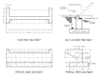
West Abutment Design


Section Abutment
Section Lateral